Steel Beam Sizes Chart PDF⁚ A Comprehensive Guide
A steel beam sizes chart PDF is an invaluable resource for engineers, architects, and contractors involved in structural design and construction. This comprehensive guide provides detailed information on various steel beam types, their dimensions, and properties, enabling accurate selection for specific project requirements. This guide will help you understand the different aspects of steel beams, how to interpret a steel beam sizes chart PDF, and how to utilize this information for successful construction projects.
Introduction
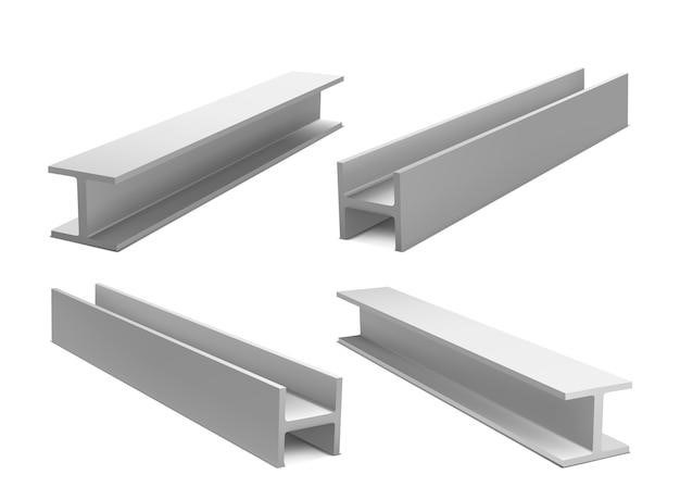
Steel beams, also known as I-beams or wide-flange beams, are fundamental structural elements used in a wide range of construction projects, from residential buildings to towering skyscrapers. They are renowned for their strength, durability, and versatility, making them a preferred choice for supporting loads, spanning openings, and creating robust frameworks. Understanding the different types of steel beams, their dimensions, and properties is crucial for engineers, architects, and contractors to ensure the stability and safety of structures. A steel beam sizes chart PDF serves as a comprehensive guide, providing detailed information about the various steel beams available, enabling professionals to select the most suitable beam for their specific project requirements.
This guide delves into the world of steel beams, explaining the different types, how to interpret a steel beam sizes chart PDF, and the key information it contains. We will explore the significance of nominal size, section dimensions, section area, unit weight, and other properties listed on the chart. Furthermore, we will discuss how to utilize this information effectively for successful construction projects, highlighting the importance of safety considerations.

By understanding the content and application of a steel beam sizes chart PDF, professionals can confidently select the appropriate steel beams, ensuring the structural integrity and longevity of their projects.
Types of Steel Beams
Steel beams are classified into various types based on their cross-sectional shape and manufacturing processes. The most common types of steel beams found on a steel beam sizes chart PDF include⁚
- Wide Flange Beams (W-beams)⁚ These are the most prevalent type of steel beam, characterized by their I-shaped cross-section with wide flanges and a web connecting them. They are widely used in a variety of structural applications due to their high strength-to-weight ratio.
- Universal Beams (UBs)⁚ Similar to W-beams, UBs are I-shaped beams commonly used in the UK and other countries using metric units. Their dimensions and properties are defined by British standards.
- American Standard Beams (S-beams)⁚ These beams have a wider flange than W-beams and are typically used for heavier loads. They are less common than W-beams but still find application in certain structural projects.
- Channel Beams (C-beams)⁚ These beams have a U-shaped cross-section and are often used for supporting floors, roofs, and walls. They are lighter than I-beams and can be used for various purposes.
- Angle Beams (L-beams)⁚ These beams have an L-shaped cross-section and are commonly used for bracing and connecting structural elements. They are versatile and can be used in various configurations.
The steel beam sizes chart PDF typically lists the dimensions and properties of each type of steel beam, allowing for proper selection based on specific project requirements.
Understanding Steel Beam Sizes
Steel beam sizes are crucial for determining the load-carrying capacity and suitability of a beam for a specific structural application. A steel beam sizes chart PDF provides detailed information on the dimensions and properties of various steel beams, allowing for informed selection. Understanding the terminology used in the chart is essential for effective use. The chart typically lists the following information for each beam size⁚
- Nominal Size⁚ This refers to the standard designation of the beam, typically represented by a combination of letters and numbers (e.g., W12x22, UB150x75). The first part indicates the beam type (W for Wide Flange, UB for Universal Beam), while the subsequent numbers indicate the nominal depth and weight per unit length.
- Section Dimensions⁚ This includes the width of the flanges, the depth of the web, and the thickness of both the flanges and the web. These dimensions are crucial for calculating the cross-sectional area and moment of inertia of the beam.
- Section Area⁚ The section area represents the total area of the beam’s cross-section and is typically expressed in square inches or square millimeters. It directly affects the beam’s strength and stiffness.
- Unit Weight⁚ This indicates the weight of the beam per unit length, typically expressed in pounds per foot (lbs/ft) or kilograms per meter (kg/m). It is essential for calculating the overall weight of the beam.
- Other Properties⁚ The chart may also include other properties, such as the moment of inertia, radius of gyration, and shear modulus. These properties are crucial for calculating the beam’s resistance to bending and twisting forces.
By carefully reviewing this information, you can choose the appropriate steel beam size for your structural needs.
Steel Beam Sizes Chart PDF⁚ Key Information

A steel beam sizes chart PDF is an organized and comprehensive document that provides crucial information about different steel beam types. This chart acts as a reference guide for engineers, architects, and contractors involved in structural design and construction. It contains essential details that enable the selection of the most suitable beam for various project requirements. The key information included in these charts typically encompasses⁚
- Nominal Size⁚ The nominal size is a standardized designation that identifies the beam type and its approximate dimensions. It usually consists of letters and numbers, like “W12x22” or “UB150x75.” The first part indicates the beam type (W for Wide Flange, UB for Universal Beam), and the following numbers represent the nominal depth and weight per unit length.
- Section Dimensions⁚ These dimensions describe the physical characteristics of the beam’s cross-section. They include the width of the flanges, the depth of the web, and the thickness of both the flanges and the web. These details are essential for calculating the beam’s cross-sectional area and moment of inertia.
- Section Area⁚ The section area represents the total area of the beam’s cross-section, typically expressed in square inches or square millimeters. This value is directly related to the beam’s strength and stiffness.
- Unit Weight⁚ The unit weight refers to the weight of the beam per unit length, usually expressed in pounds per foot (lbs/ft) or kilograms per meter (kg/m). This information is crucial for calculating the overall weight of the beam and for determining the load it can support.
- Other Properties⁚ Steel beam sizes charts may also include additional properties, such as the moment of inertia, radius of gyration, and shear modulus. These properties help engineers calculate the beam’s resistance to bending and twisting forces, ensuring structural stability.
By understanding these key elements, professionals can effectively utilize the information provided in the steel beam sizes chart PDF to make informed decisions regarding the selection and application of appropriate beams in their projects.
Nominal Size
The nominal size is a standardized designation that provides a quick and easy way to identify a specific steel beam type and its approximate dimensions. It’s like a shorthand code that engineers and contractors use to communicate about beams without having to list all the detailed dimensions. The nominal size is typically presented as a combination of letters and numbers, such as “W12x22” or “UB150x75.” Each part of this designation holds specific meaning⁚
- Letters⁚ The letters indicate the type of beam. For example, “W” stands for Wide Flange, a common type of steel beam used in construction. Other common letters include “UB” for Universal Beam, “S” for Standard Beam, and “C” for Channel.
- Numbers⁚ The numbers represent the nominal depth and weight per unit length. The first number usually refers to the approximate depth of the beam in inches or millimeters (e.g., 12 inches for “W12x22” or 150 millimeters for “UB150x75”). The second number represents the approximate weight of the beam per foot or meter. For instance, “W12x22” indicates a beam that weighs approximately 22 pounds per foot, and “UB150x75” represents a beam that weighs approximately 75 kilograms per meter.
The nominal size is a convenient way to quickly identify and compare different beam types based on their size and weight. However, it’s important to note that the actual dimensions of the beam may slightly vary from the nominal size. For precise measurements and other important properties, refer to the detailed information provided in the steel beam sizes chart PDF.
Section Dimensions
The section dimensions provide a detailed breakdown of the physical shape and size of the steel beam. This information is crucial for accurate structural calculations and ensuring proper fit during construction. The section dimensions typically include the following measurements⁚
- Depth (D)⁚ This is the vertical distance between the top and bottom flanges of the beam, measured in inches or millimeters. It’s often the same or close to the nominal depth indicated in the beam designation.
- Flange Width (W)⁚ This represents the horizontal width of the top and bottom flanges, measured in inches or millimeters. The flange width significantly influences the beam’s bending strength and its ability to resist lateral buckling.
- Web Thickness (TW)⁚ This measurement refers to the thickness of the vertical web connecting the top and bottom flanges, measured in inches or millimeters. The web thickness plays a crucial role in the beam’s shear strength and its ability to withstand vertical loads.
- Flange Thickness (TF)⁚ This measurement indicates the thickness of the top and bottom flanges, measured in inches or millimeters. The flange thickness contributes to the beam’s overall stiffness and its resistance to bending.
- Corner Radius (R)⁚ This measurement indicates the radius of the rounded corners where the flanges meet the web, measured in inches or millimeters. The corner radius helps to distribute stresses and improve the beam’s fatigue resistance.
The detailed section dimensions are essential for structural engineers and designers to determine the beam’s load-carrying capacity, its resistance to various stresses, and its compatibility with other structural components. These measurements are also critical for fabricators and contractors to ensure accurate cutting, welding, and installation of the steel beams.
Section Area
The section area, also known as the cross-sectional area, represents the total area of the steel beam’s cross-section. This crucial parameter is measured in square inches (in²) or square millimeters (mm²) and is vital for various structural calculations, particularly when determining the beam’s weight and its resistance to various stresses.
The section area is calculated by multiplying the beam’s width by its depth, considering the shape of the cross-section. For wide flange beams, the calculation involves adding the areas of the flanges and the web, taking into account the rounded corners. The section area is directly proportional to the amount of steel used in the beam, making it a significant factor in the beam’s weight and cost.
The section area is also crucial for calculating the beam’s moment of inertia, which represents its resistance to bending. A larger section area generally results in a higher moment of inertia, indicating a stronger ability to withstand bending stresses. The section area, along with other properties like the material’s yield strength, is essential for engineers to determine the beam’s load-carrying capacity and its suitability for specific applications.
Unit Weight
The unit weight, often referred to as the weight per unit length, is a crucial parameter listed on a steel beam sizes chart PDF. It represents the weight of a one-foot or one-meter section of the beam, providing essential information for structural design and construction. This weight is typically expressed in pounds per linear foot (lb/ft) or kilograms per linear meter (kg/m), allowing for accurate calculations of the overall weight of the beam based on its length.
The unit weight is directly related to the beam’s section area and the density of the steel used in its construction. A larger section area generally results in a heavier beam, while denser steel will contribute to a higher unit weight. The unit weight is a critical factor in structural design, as it influences the overall load on supports and the foundation, as well as the weight of the structure itself.
Engineers and contractors utilize the unit weight to determine the weight of the steel beams used in a project, enabling them to accurately calculate the total load on the structure, including the weight of the beams and the loads they will carry. This information is essential for ensuring the stability and safety of the structure, as well as for planning transportation and handling requirements for the steel beams.
Other Properties
Steel beam sizes chart PDFs often include additional properties beyond nominal size, section dimensions, area, and unit weight. These properties provide further insights into the beam’s behavior under load and are crucial for informed structural design and engineering. These properties might include⁚
- Moment of Inertia (I)⁚ This property measures a beam’s resistance to bending. A higher moment of inertia indicates greater resistance to deformation under load, making the beam suitable for spanning larger distances or supporting heavier loads.
- Section Modulus (S)⁚ The section modulus is a measure of a beam’s resistance to bending stress. A higher section modulus signifies greater strength and the ability to withstand higher bending stresses.
- Radius of Gyration (r)⁚ This property describes the distribution of a beam’s cross-sectional area relative to its neutral axis. It influences a beam’s resistance to buckling under compressive loads.
- Shear Strength (τ)⁚ Shear strength refers to the beam’s capacity to resist forces acting parallel to its cross-section. This property is essential for understanding how the beam will behave under shear loads.
These additional properties provide valuable information to engineers and architects, enabling them to select the most appropriate steel beam for a specific application based on the anticipated loads, bending requirements, and other critical factors. A thorough understanding of these properties ensures the stability and safety of any structure using steel beams.